Soldering Temperatures for PCB Assembly
PCB soldering requires precise temperature control for reliable connections. Techniques like SMT and reflow soldering use specific temperature profiles to ensure quality.
The manufacturing process of a printed circuit board is highly complex, which rests on twin pillars of precision and reliability. In the middle of all this is soldering-a process through which the individual electronic components get strongly attached to the printed circuit board. The temperature during the process of soldering has always been a crucial concern that does not only implicate the integrity of joints but the entire performance of the device. The article covers the best temperature ranges for different methods of PCB assembly, conditions defining the temperature, and relating to product reliability.
The process of soldering is helped by a metal alloy composed of mainly tin and either lead or other non-toxic metals like silver and copper for its lead-free versions; The melting point of any alloy determines the temperature towards its soldering, as in different techniques and different materials.
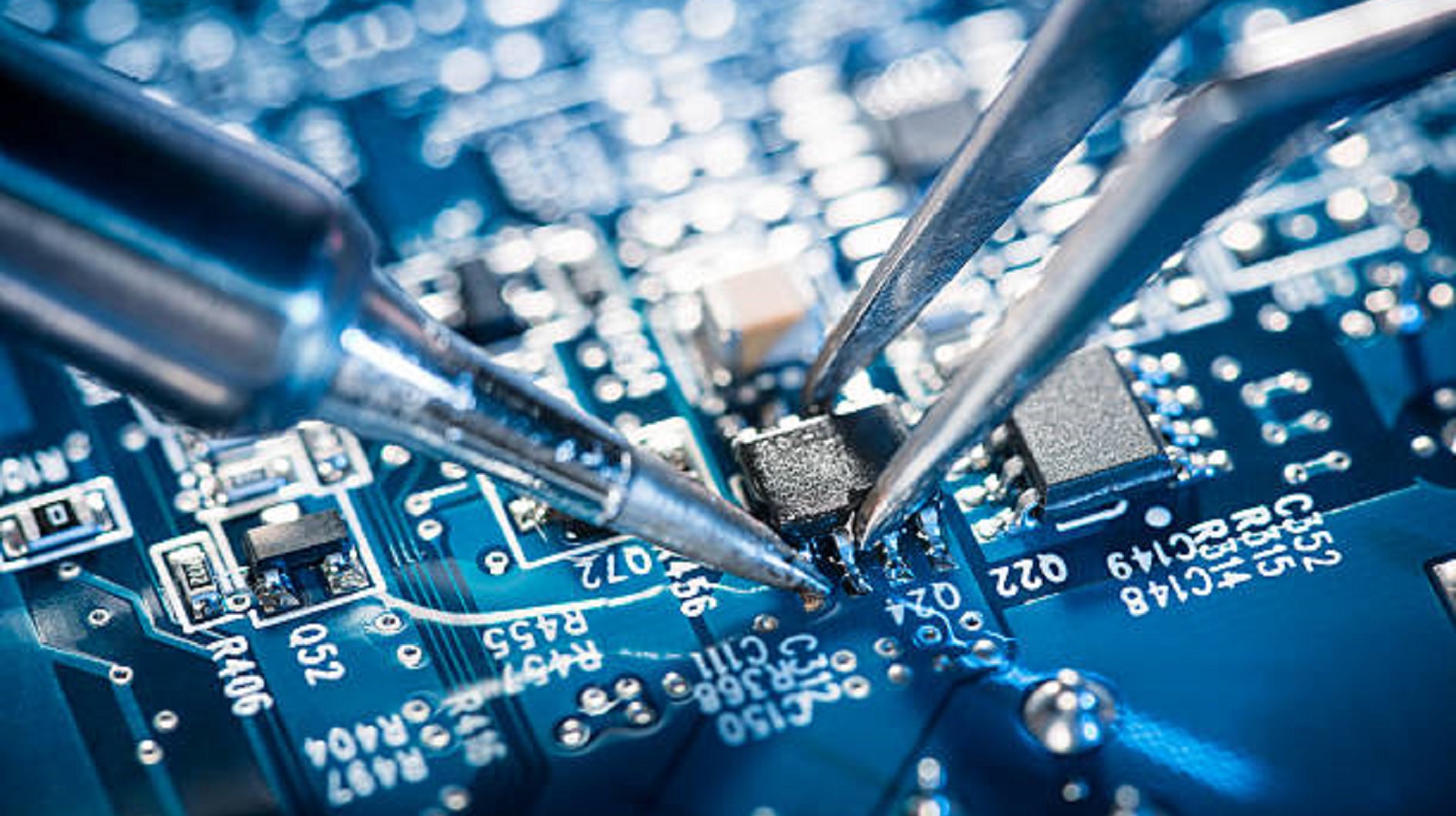
Surface-Mount Technology
Surface-mount technology is among the dominating technologies in the present assembly of PCB. By this technology, components attach directly to a PCB surface. Usual temperatures are from 220°C to 250°C, but an exacting requirement will be determined by the used reflow or wave soldering method:
Reflow Soldering: The three-stage thermal profile for this process includes preheating, soaking, and reflow. Preheating (80-150°C) acclimatizes the board to higher temperatures. Soaking at 150-220°C ensures that solder paste is evenly distributed. Reflow at 210-260°C melts the solder, thereby securing the components firmly. The use of lead-free soldering requires temperatures between 240°C and 260°C because these materials have higher melting points.
Wave Soldering: This will typically involve through-hole components with the solder pot temperature at around 288±5°C. Preheating will be needed to minimize thermal shock, together with ensuring quality solder joints.
Through-Hole Soldering
This traditional technique is imperative in larger components that require strong connections. The temperature here ranges between 250°C and 300°C. This allows the solder to adequately pass through the holes resulting in sufficient mechanical and electrical bonds.
Copper Foil Soldering
In applications involving high power or multilayer boards, copper foil needs to be soldered. The temperature, in this case, is from 280°C to 330°C. Heavier and more conductive, higher temperatures are needed for copper to reach favorable soldering conditions.
Manual Soldering
Manual soldering also allows for more precise and focused heating. The temperature can generally be maintained between 240°C to 280°C, possibly even up to 350°C or 370°C in the case of larger components, although temperatures in excess of 390°C risk overheating and may cause damage to both the PCB and its components.
Stages of Soldering Process
Temperature control during soldering is categorized into several critical stages of the process that are necessary for high-quality results:
Preheating Stage
This step will gradually increase the temperature of the PCB and the components to avoid thermal shock and also provides uniform heat distribution. The preheat temperatures can be between 80-120°C for lead-based solders and between 100-150°C for lead-free alternatives.
Soaking Stage
This stage keeps the board in a uniform temperature, which is sufficiently long for all areas of solder paste distribution to wet the leads and pads effectively. The temperature at which soaking typically is done is within 150-180°C for lead-based and 180-220°C for lead-free solders. The time is varied from 30-60 seconds depending on the thermal mass of the board and the components.
Reflow Stage
This stage, the reflow stage, is an important stage at which the solder paste is taken to its melting point, hence solidifying the connection between the components and the PCB. Typical temperatures are between 210-240°C for lead solder and between 240-260°C for lead-free solder; generally, it lasts from 20 to 40 seconds. Careful control is done so that components are not damaged or displaced by thermal expansion.
Cooling Stage
Gradual cooling reduces thermal stresses to ensure that the structure of the package is maintained. The ideal rate should be 4-6°C per second in order to reduce the risk of mechanical stresses that can weaken the solder joints.
Risks Associated with High-Temperature Soldering
High-temperature soldering is absolutely necessary to obtain reliable joints but is also a potential risk, mainly for inner PCB layers. The main origins of the risks are linked to:
Thermal Stress: Rapid temperature changes can cause material expansion and contraction, possibly leading to inner layer cracks or breaks.
Material Compatibility: Using materials with unmatched coefficients of thermal expansion can exacerbate thermal stress effects.
Process Control: Poor management of soldering parameters, particularly temperature, can lead to defects such as joint deformation, insulation damage, or circuit failure.
Mitigating High-Temperature Soldering Risks
To safeguard PCB integrity:
Select Appropriate Materials: Ensure materials used have compatible thermal expansion properties.
Optimize Process Parameters: Control temperature, time, and cooling rates carefully.
Design Considerations: Make prudent designs considering thermal impacts, especially in sensitive areas of the PCBs.
Testing: Run periodic thermal stress tests to identify any weak points or vulnerabilities so that corrective measures can be made on time.
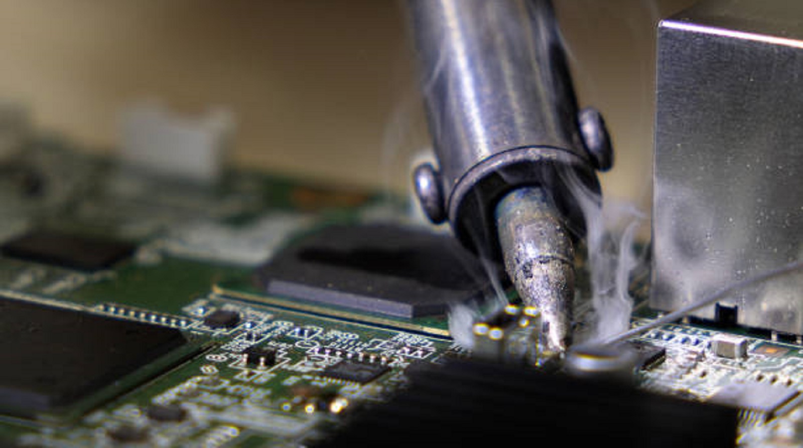
Temperature control in the soldering of a PCB is essential to formulate high-quality, reliable connections. By correlating the choice of soldering techniques with component types and materials using appropriate soldering profiles, we ensure the integrity of our products for long useful life. At PCBX, we remain committed to making use of our expertise in leading technologies to deliver products that achieve the highest standards of quality and reliability.
Hot Tags:
Contact us

If you can't find what you're looking for, please contact us.
Article
Cold solder joints result from improper soldering, impacting PCB performance. Detection and prevention via proper technique and equipment ensure reliability.
SMD soldering mounts small components on the PCB surface for compact, automated designs but has high setup costs and repair challenges. DIP soldering uses through-hole components for robust, easily repairable, lower-volume applications.
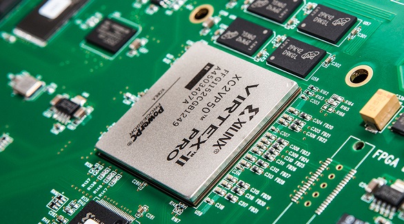
Ball Grid Array (BGA) components, such as PBGA, CBGA, CCGA, TBGA, and CSP, provide high I/O density, improved reliability, and high-quality electrical and thermal performance. Quality assembly and functionality are assured since advanced soldering and inspection methods are required, like AXI and AOI. Proper storage and handling shall guarantee the performance of the devices.
